

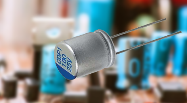
1. Electrolytic capacitors
Electrolytic capacitors are capacitors formed by the oxidation layer on the electrode through the action of the electrolyte as an insulating layer, which usually has a large capacity. The electrolyte is a liquid, jelly-like material rich in ions, and most electrolytic capacitors are polar, that is, when working, the voltage of the positive electrode of the capacitor needs to be always higher than the negative voltage.
The high capacity of electrolytic capacitors is also sacrificed for many other characteristics, such as having a large leakage current, a large equivalent series inductance and resistance, a large tolerance error, and a short life.
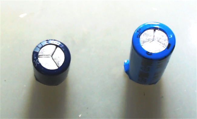
In addition to polar electrolytic capacitors, there are also non-polar electrolytic capacitors. In the figure below, there are two kinds of 1000uF, 16V electrolytic capacitors. Among them, the larger is non-polar, and the smaller is polar.
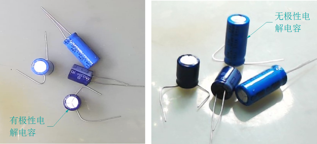
(Non-polar and polar electrolytic capacitors)
The inside of the electrolytic capacitor may be a liquid electrolyte or a solid polymer, and the electrode material is commonly Aluminum (Aluminum) or tantalum (Tandalum). The following is a common polar aluminum electrolytic capacitor inside the structure, between the two layers of electrodes there is a layer of fiber paper soaked in electrolyte, plus a layer of insulating paper turned into a cylinder, sealed in the aluminum shell.
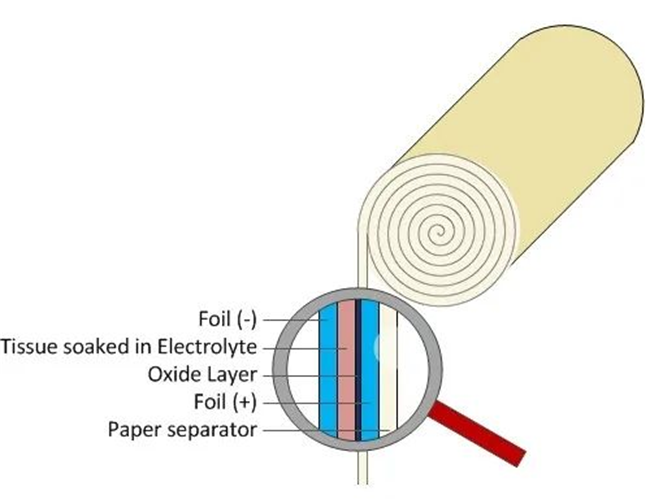
(Internal structure of electrolytic capacitor)
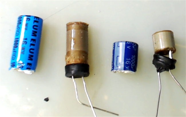
Dissecting the electrolytic capacitor, its basic structure can be clearly seen. In order to prevent the evaporation and leakage of the electrolyte, the capacitor pin part is fixed with sealing rubber.
Of course, the figure also shows the difference in internal volume between polar and non-polar electrolytic capacitors. At the same capacity and voltage level, the non-polar electrolytic capacitor is about twice as large as the polar one.
(Internal structure of non-polar and polar electrolytic capacitors)
This difference mainly comes from the large difference in the area of the electrodes inside the two capacitors. The non-polar capacitor electrode is on the left and the polar electrode is on the right. In addition to the area difference, the thickness of the two electrodes is also different, and the thickness of the polar capacitor electrode is thinner.

(Electrolytic capacitor aluminum sheet of different width)
2. Capacitor explosion
When the voltage applied by the capacitor exceeds its withstand voltage, or when the polarity of the voltage of the polar electrolytic capacitor is reversed, the capacitor leakage current will rise sharply, resulting in an increase in the internal heat of the capacitor, and the electrolyte will produce a large amount of gas.
In order to prevent capacitor explosion, there are three grooves pressed on the top of the capacitor housing, so that the top of the capacitor is easy to break under high pressure and release the internal pressure.
(Blasting tank at the top of electrolytic capacitor)
However, some capacitors in the production process, the top groove pressing is not qualified, the pressure inside the capacitor will make the sealing rubber at the bottom of the capacitor is ejected, at this time the pressure inside the capacitor is suddenly released, will form an explosion.
1, non-polar electrolytic capacitor explosion
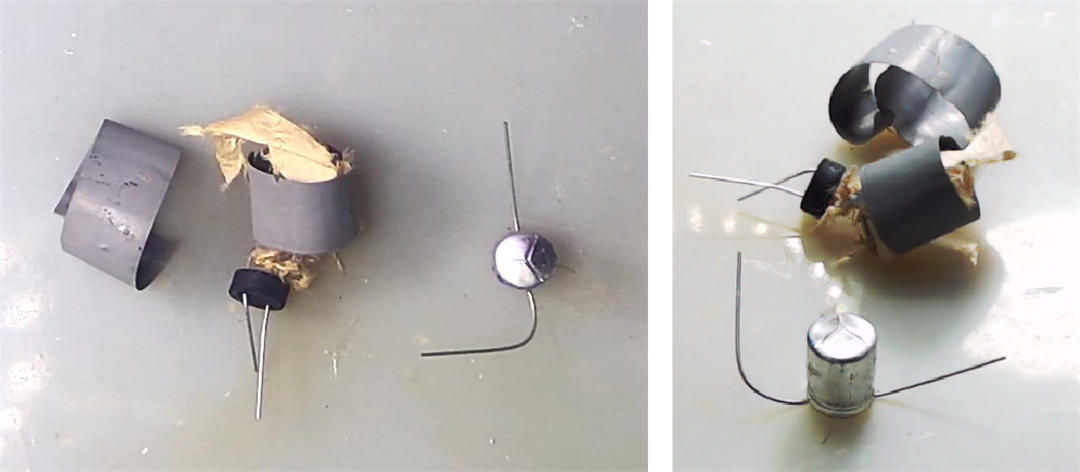
The figure below shows a non-polar electrolytic capacitor at hand, with a capacity of 1000uF and a voltage of 16V. After the applied voltage exceeds 18V, the leakage current suddenly increases, and the temperature and pressure inside the capacitor increase. Eventually, the rubber seal at the bottom of the capacitor bursts open, and the internal electrodes are smashed loose like popcorn.
(non-polar electrolytic capacitor overvoltage blasting)
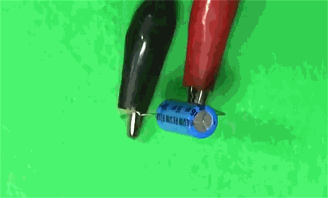
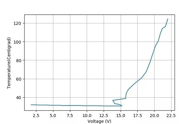
By tying a thermocouple to a capacitor, it is possible to measure the process by which the temperature of the capacitor changes as the applied voltage increases. The following figure shows the non-polar capacitor in the process of voltage increase, when the applied voltage exceeds the withstand voltage value, the internal temperature continues to increase process.
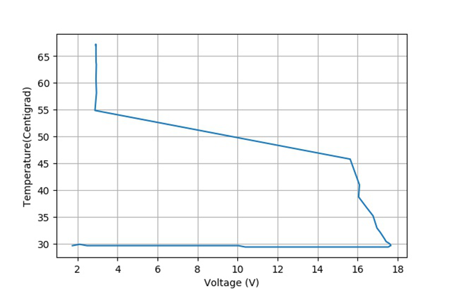
(Relationship between voltage and temperature)
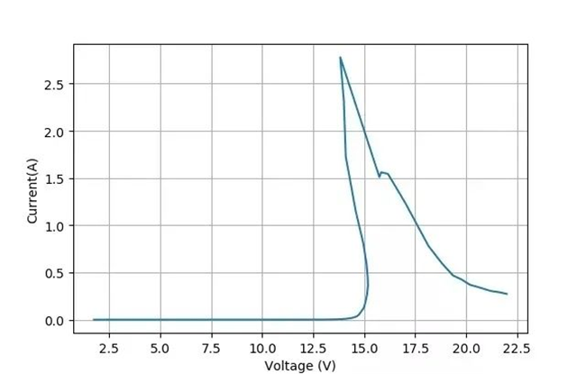
The figure below shows the change in the current flowing through the capacitor during the same process. It can be seen that the increase in current is the main reason for the rise in internal temperature. In this process, the voltage is linearly increased, and as the current rises sharply, the power supply group makes the voltage drop. Finally, when the current exceeds 6A, the capacitor explodes with a loud bang.
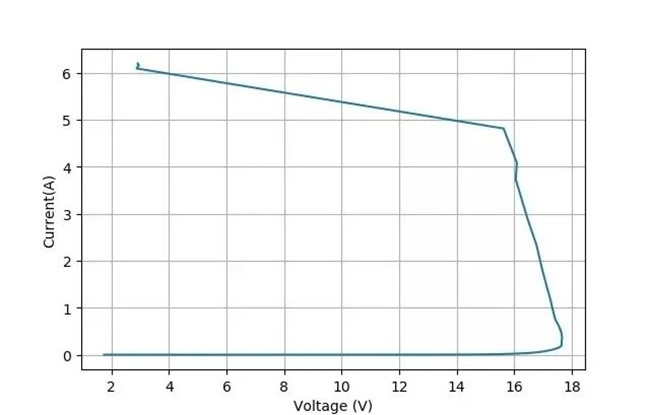
(Relationship between voltage and current)
Due to the large internal volume of the non-polar electrolytic capacitor and the amount of electrolyte, the pressure generated after the overflow is huge, resulting in the pressure relief tank at the top of the shell not breaking, and the sealing rubber at the bottom of the capacitor is blown open.
2, polar electrolytic capacitor explosion
For polar electrolytic capacitors, a voltage is applied. When the voltage exceeds the withstand voltage of the capacitor, the leakage current will also rise sharply, causing the capacitor to overheat and explode.
The figure below shows the limiting electrolytic capacitor, which has a capacity of 1000uF and a voltage of 16V. After overvoltage, the internal pressure process is released through the top pressure relief tank, so the capacitor explosion process is avoided.
The following figure shows how the temperature of the capacitor changes with the increase of the applied voltage. As the voltage gradually approaches the withstand voltage of the capacitor, the residual current of the capacitor increases, and the internal temperature continues to rise.
(Relationship between voltage and temperature)
The following figure is the change of the leakage current of the capacitor, the nominal 16V electrolytic capacitor, in the test process, when the voltage exceeds 15V, the leakage of the capacitor begins to rise sharply.
(Relationship between voltage and current)
Through the experimental process of the first two electrolytic capacitors, it can also be seen that the voltage limit of such 1000uF ordinary electrolytic capacitors. In order to avoid high-voltage breakdown of the capacitor, when using the electrolytic capacitor, it is necessary to leave enough margin according to the actual voltage fluctuations.
3,electrolytic capacitors in series
Where appropriate, greater capacitance and greater capacitance withstand voltage can be obtained by parallel and series connection, respectively.
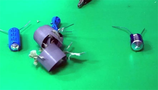
(electrolytic capacitor popcorn after overpressure explosion)
In some applications, the voltage applied to the capacitor is AC voltage, such as coupling capacitors of speakers, alternating current phase compensation, motor phase-shifting capacitors, etc., requiring the use of non-polar electrolytic capacitors.
In the user manual given by some capacitor manufacturers, it is also given that the use of traditional polar capacitors by back-to-back series, that is, two capacitors in series together, but the polarity is opposite to obtain the effect of non-polar capacitors.
(electrolytic capacitance after overvoltage explosion)
The following is a comparison of the polar capacitor in the application of forward voltage, reverse voltage, two electrolytic capacitors back-to-back series into three cases of non-polar capacitance, leakage current changes with the increase of the applied voltage.
1. Forward voltage and leakage current
The current flowing through the capacitor is measured by connecting a resistor in series. Within the voltage tolerance range of the electrolytic capacitor (1000uF, 16V), the applied voltage is gradually increased from 0V to measure the relationship between the corresponding leakage current and voltage.
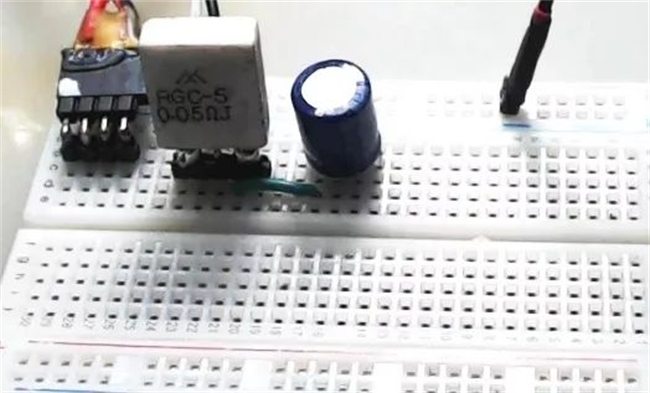
(positive series capacitance)
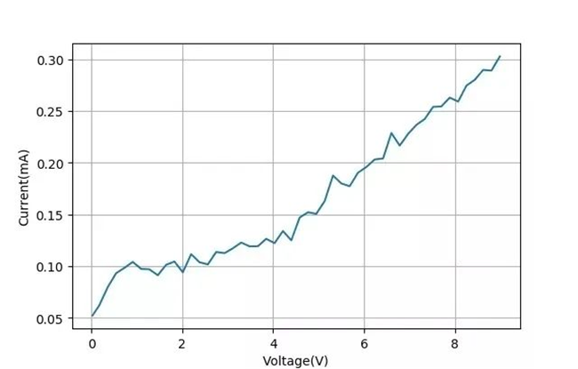
The following figure shows the relationship between the leakage current and voltage of a polar aluminum electrolytic capacitor, which is a nonlinear relationship with the leakage current below 0.5mA.
(The relationship between voltage and current after the forward series)
2, reverse voltage and leakage current
Using the same current to measure the relationship between the applied direction voltage and the electrolytic capacitor leakage current, it can be seen from the figure below that when the applied reverse voltage exceeds 4V, the leakage current begins to increase rapidly. From the slope of the following curve, the reverse electrolytic capacitance is equivalent to a resistance of 1 ohms.

(Reverse voltage Relationship between voltage and current)
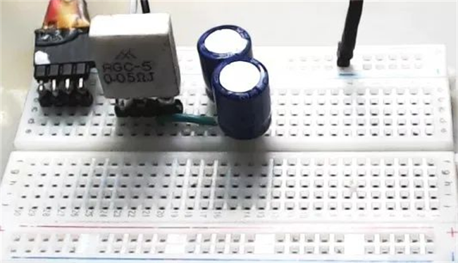
3. Back-to-back series capacitors
Two identical electrolytic capacitors (1000uF, 16V) are connected back-to-back in series to form a non-polar equivalent electrolytic capacitor, and then the relationship curve between their voltage and leakage current is measured.
(positive and negative polarity series capacitance)
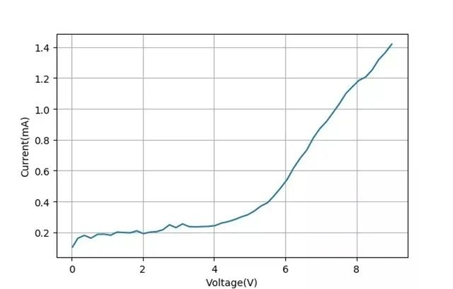
The following diagram shows the relationship between the capacitor voltage and the leakage current, and you can see that the leakage current increases after the applied voltage exceeds 4V, and the current amplitude is less than 1.5mA.
And this measurement is a little surprising, because you see that the leakage current of these two back-to-back series capacitors is actually greater than the leakage current of a single capacitor when the voltage is applied forward.
(The relationship between voltage and current after positive and negative series)
However, due to time reasons, there was no repeated test for this phenomenon. Perhaps one of the capacitors used was the capacitor of the reverse voltage test just now, and there was damage inside, so the above test curve was generated.
Post time: Jul-25-2023


