

Filter capacitors, common-mode inductors, and magnetic beads are common figures in EMC design circuits, and are also three powerful tools to eliminate electromagnetic interference.
For the role of these three in the circuit, I believe there are many engineers do not understand, the article from the design of a detailed analysis of the principle of eliminating the three EMC sharpest.
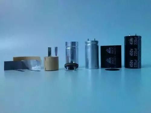
1.Filter capacitor
Although the resonance of the capacitor is undesirable from the point of view of filtering out high-frequency noise, the resonance of the capacitor is not always harmful.
When the frequency of the noise to be filtered is determined, the capacity of the capacitor can be adjusted so that the resonant point just falls on the disturbance frequency.
In practical engineering, the frequency of electromagnetic noise to be filtered is often as high as hundreds of MHz, or even more than 1GHz. For such high frequency electromagnetic noise, it is necessary to use a through-core capacitor to effectively filter out.
The reason why ordinary capacitors cannot effectively filter out high-frequency noise is because of two reasons:
(1) One reason is that the inductance of the capacitor lead causes capacitor resonance, which presents a large impedance to the high-frequency signal, and weakens the bypass effect of the high-frequency signal;
(2) Another reason is that the parasitic capacitance between the wires coupling the high-frequency signal, reducing the filtering effect.
The reason why the through-core capacitor can effectively filter out high-frequency noise is that the through-core capacitor not only does not have the problem that the lead inductance causes the capacitor resonance frequency is too low.
And the through-core capacitor can be directly installed on the metal panel, using the metal panel to play the role of high-frequency isolation. However, when using the through-core capacitor, the problem to pay attention to is the installation problem.
The biggest weakness of the through-core capacitor is the fear of high temperature and temperature impact, which causes great difficulties when welding the through-core capacitor to the metal panel.
Many capacitors are damaged during welding. Especially when a large number of core capacitors need to be installed on the panel, as long as there is a damage, it is difficult to repair, because when the damaged capacitor is removed, it will cause damage to other nearby capacitors.
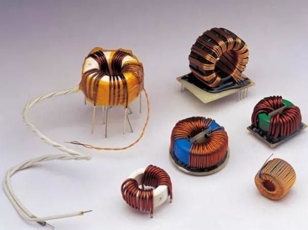
2.Common mode inductance
Since the problems EMC faces are mostly common mode interference, common mode inductors are also one of our commonly used powerful components.
The common mode inductor is a common mode interference suppression device with ferrite as the core, which consists of two coils of the same size and the same number of turns symmetrically wound on the same ferrite ring magnetic core to form a four-terminal device, which has a large inductance suppression effect for the common mode signal, and a small leakage inductance for the differential mode signal.
The principle is that when the common mode current flows, the magnetic flux in the magnetic ring superimposes each other, thus having a considerable inductance, which inhibits the common mode current, and when the two coils flow through the differential mode current, the magnetic flux in the magnetic ring cancels each other, and there is almost no inductance, so the differential mode current can pass without attenuation.
Therefore, the common mode inductor can effectively suppress the common mode interference signal in the balanced line, but has no effect on the normal transmission of the differential mode signal.
Common mode inductors should meet the following requirements when they are manufactured:
(1) The wires wound on the coil core should be insulated to ensure that there is no breakdown short circuit between turns of the coil under the action of instantaneous overvoltage;
(2) When the coil flows through the instantaneous large current, the magnetic core should not be saturated;
(3) The magnetic core in the coil should be insulated from the coil to prevent breakdown between the two under the action of instantaneous overvoltage;
(4) The coil should be wound in a single layer as far as possible, so as to reduce the parasitic capacitance of the coil and enhance the ability of the coil to transmit transient overvoltage.
Under normal circumstances, while paying attention to the selection of the frequency band required to filter, the larger the common-mode impedance, the better, so we need to look at the device data when selecting the common-mode inductor, mainly according to the impedance frequency curve.
In addition, when selecting, pay attention to the impact of differential mode impedance on the signal, mainly focusing on differential mode impedance, especially paying attention to high-speed ports.
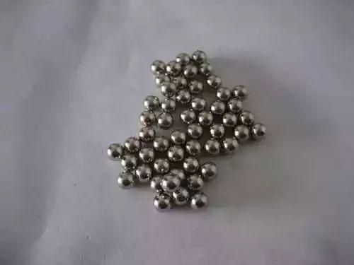
3.Magnetic bead
In the product digital circuit EMC design process, we often use magnetic beads, ferrite material is iron-magnesium alloy or iron-nickel alloy, this material has a high magnetic permeability, he can be the inductor between the coil winding in the case of high frequency and high resistance generated capacitance minimum.
Ferrite materials are usually used at high frequencies, because at low frequencies their main inductance characteristics make the loss on the line very small. At high frequencies, they are mainly reactance characteristic ratios and change with frequency. In practical applications, ferrite materials are used as high frequency attenuators for radio frequency circuits.
In fact, ferrite is better equivalent to the parallel of resistance and inductance, the resistance is short-circuited by the inductor at low frequency, and the inductor impedance becomes quite high at high frequency, so that the current all passes through the resistance.
Ferrite is an consuming device on which high-frequency energy is converted into heat energy, which is determined by its electrical resistance characteristics. Ferrite magnetic beads have better high-frequency filtering characteristics than ordinary inductors.
Ferrite is resistive at high frequencies, equivalent to an inductor with a very low quality factor, so it can maintain a high impedance over a wide frequency range, thereby improving the efficiency of high frequency filtering.
In the low frequency band, the impedance is composed of inductance. At low frequency, R is very small, and the magnetic permeability of the core is high, so the inductance is large. L plays a major role, and electromagnetic interference is suppressed by reflection. And at this time, the loss of the magnetic core is small, the entire device is a low loss, high Q characteristics of the inductor, this inductor is easy to cause resonance, so in the low frequency band, sometimes there may be enhanced interference after the use of ferrite magnetic beads.
In the high frequency band, the impedance is composed of resistance components. As the frequency increases, the permeability of the magnetic core decreases, resulting in a decrease in the inductance of the inductor and a decrease in the inductive reactance component.
However, at this time, the loss of the magnetic core increases, the resistance component increases, resulting in an increase in the total impedance, and when the high-frequency signal passes through the ferrite, the electromagnetic interference is absorbed and converted into the form of heat dissipation.
Ferrite suppression components are widely used in printed circuit boards, power lines and data lines. For example, a ferrite suppression element is added to the inlet end of the power cord of the printed board to filter out high-frequency interference.
Ferrite magnetic ring or magnetic bead is specially used to suppress high-frequency interference and peak interference on signal lines and power lines, and it also has the ability to absorb electrostatic discharge pulse interference. The use of chip magnetic beads or chip inductors mainly depends on the practical application.
Chip inductors are used in resonant circuits. When unnecessary EMI noise needs to be eliminated, the use of chip magnetic beads is the best choice.
Application of chip magnetic beads and chip inductors
Chip inductors: Radio frequency (RF) and wireless communications, information technology equipment, radar detectors, automotive electronics, cellular phones, pagers, audio equipment, personal digital assistants (PDAs), wireless remote control systems, and low-voltage power supply modules.
Chip magnetic beads: Clock-generating circuits, filtering between analog and digital circuits, I/O input/output internal connectors (such as serial ports, parallel ports, keyboards, mice, long-distance telecommunications, local area networks), RF circuits and logic devices susceptible to interference, filtering of high-frequency conducted interference in power supply circuits, computers, printers, video recorders (VCRS), EMI noise suppression in television systems and mobile phones.
The unit of the magnetic bead is ohms, because the unit of the magnetic bead is nominal in accordance with the impedance it produces at a certain frequency, and the unit of impedance is also ohms.
The magnetic bead DATASHEET will generally provide the frequency and impedance characteristics of the curve, generally 100MHz as the standard, for example, when the frequency of 100MHz when the impedance of the magnetic bead is equivalent to 1000 ohms.
For the frequency band we want to filter, we need to choose the larger the impedance of the magnetic bead, the better, usually choose 600 ohm impedance or more.
In addition, when selecting magnetic beads, it is necessary to pay attention to the flux of magnetic beads, which generally needs to be derated by 80%, and the influence of DC impedance on voltage drop should be considered when used in power circuits.
Post time: Jul-24-2023


