

Many projects of hardware engineers are completed on the hole board, but there is the phenomenon of accidentally connecting the positive and negative terminals of the power supply, which leads to many electronic components burning, and even the whole board is destroyed, and it has to be welded again, I do not know what good way to solve it?
First of all, carelessness is inevitable, although it is only to distinguish the positive and negative two wires, a red and a black, may be wired once, we will not make mistakes; Ten connections won’t go wrong, but 1,000? What about 10,000? At this time it is hard to say, due to our carelessness, leading to some electronic components and chips burned out, the main reason is that the current is too much ambassador components are broken down, so we must take measures to prevent the reverse connection.
There are the following methods commonly used:
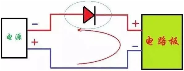
01 diode series type anti-reverse protection circuit
A forward diode is connected in series at the positive power input to make full use of the diode’s characteristics of forward conduction and reverse cutoff. Under normal circumstances, the secondary tube conducts and the circuit board works.
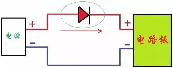
When the power supply is reversed, the diode is cut off, the power supply cannot form a loop, and the circuit board does not work, which can effectively prevent the problem of the power supply.
02 Rectifier bridge type anti-reverse protection circuit
Use the rectifier bridge to change the power input into a non-polar input, whether the power supply is connected or reversed, the board works normally.
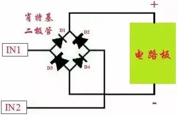
If the silicon diode has a pressure drop of about 0.6~0.8V, the germanium diode also has a pressure drop of about 0.2~0.4V, if the pressure drop is too large, the MOS tube can be used for anti-reaction treatment, the pressure drop of the MOS tube is very small, up to a few milliohm, and the pressure drop is almost negligible.
03 MOS tube anti-reverse protection circuit
MOS tube due to process improvement, its own properties and other factors, its conducting internal resistance is small, many are milliohm level, or even smaller, so that the circuit voltage drop, power loss caused by the circuit is particularly small, or even negligible, so choose MOS tube to protect the circuit is a more recommended way.
1) NMOS protection
As shown below: At the moment of power-on, the parasitic diode of the MOS tube is switched on, and the system forms a loop. The potential of the source S is about 0.6V, while the potential of the gate G is Vbat. The opening voltage of the MOS tube is extremely: Ugs = Vbat-Vs, the gate is high, the ds of NMOS is on, the parasitic diode is short-circuited, and the system forms a loop through the ds access of NMOS.
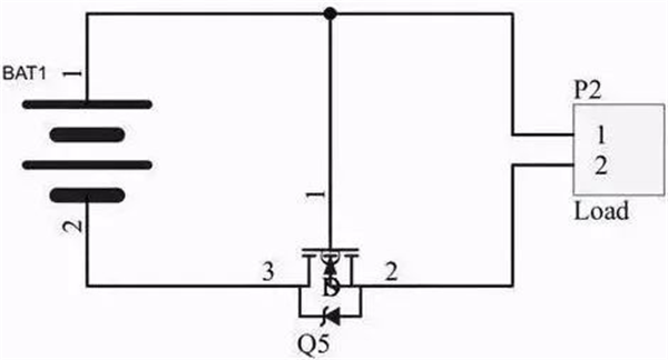
If the power supply is reversed, the on-voltage of the NMOS is 0, the NMOS is cut off, the parasitic diode is reversed, and the circuit is disconnected, thus forming protection.
2) PMOS protection
As shown below: At the moment of power-on, the parasitic diode of the MOS tube is switched on, and the system forms a loop. The potential of the source S is about Vbat-0.6V, while the potential of the gate G is 0. The opening voltage of the MOS tube is extremely: Ugs = 0 – (Vbat-0.6), the gate behaves as a low level, the ds of PMOS is on, the parasitic diode is short-circuited, and the system forms a loop through the ds access of PMOS.
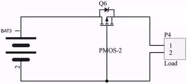
If the power supply is reversed, the on-voltage of the NMOS is greater than 0, the PMOS is cut off, the parasitic diode is reversed, and the circuit is disconnected, thus forming protection.
Note: NMOS tubes string ds to the negative electrode, PMOS tubes string ds to the positive electrode, and the parasitic diode direction is toward the correctly connected current direction.
The access of the D and S poles of the MOS tube: usually when the MOS tube with N channel is used, the current generally enters from the D pole and flows out from the S pole, and the PMOS enters and D exits from the S pole, and the opposite is true when applied in this circuit, the voltage condition of the MOS tube is met through the conduction of the parasitic diode.
The MOS tube will be fully switched on as long as a suitable voltage is established between the G and S poles. After conducting, it is like a switch is closed between D and S, and the current is the same resistance from D to S or S to D.
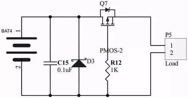
In practical applications, the G pole is generally connected with a resistor, and in order to prevent the MOS tube from being broken down, a voltage regulator diode can also be added. A capacitor connected in parallel to a divider has a soft-start effect. At the moment the current begins to flow, the capacitor is charged and the voltage of the G pole is gradually built up.
For PMOS, compared with NOMS, Vgs is required to be greater than the threshold voltage. Because the opening voltage can be 0, the pressure difference between DS is not large, which is more advantageous than NMOS.
04 Fuse protection
Many common electronic products can be seen after opening the power supply part with a fuse, in the power supply is reversed, there is a short circuit in the circuit due to large current, and then the fuse is blown, play a role in protecting the circuit, but this way repair and replacement is more troublesome.
Post time: Jul-08-2023


